Retrofitting a garage door opener
Being a home owner comes with a lot of responsibilities. You want to create an environment where your family can feel safe and at ease. For me, this was a great opportunity to do some atomization. Because I’m lazy.
When we moved in, the garage door already had a motor installed that worked, but not perfectly. Sometimes the motor was having trouble closing the door completely, which every night raised the question; is the garage door closed?
The Marantec 220 Comfort does not stand out in any way really. It’s a remote controlled motor with a few interfaces but it does not speak TCP, yet.
- Carousel LED display
- External impulse button
- Photocell for obstacle detection
- Remote receiver using 868 Mhz radio
- RJ11 connector for external control elements with system cabling
- Signal light to reflect a single state of your choosing.
The procedure should be reversible, using as few components as possible.
There is an expensive extension board
The manual points to an accessory part called No. 152133. This is a relay
board that latches when the door is open or closed. I contacted a local reseller
for Marantec and got a hefty price tag back. Ok, let’s try something else.
Reading the carousel LED display
I mounted a Raspberry Pi Zero W equipped with a camera to capture the different states represented by eight (8) LED’s. Gathered and labeled a lot of states to train a classifier.
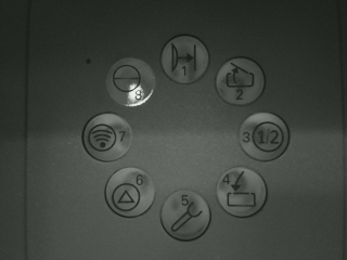
Eventually, this worked quite well to determine the garage door position. Unfortunately, without even more training data, this method was very fragile. Different lighting conditions or a small nudge to the camera mount would totally throw it off. I needed a more robust solution.
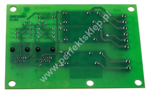
A second look at that expensive extension board
By just looking at the photos of the board provided by an online reseller, nothing fancy is going on there. Three (3) relays accompanied by resistors and diodes to protect from flyback.
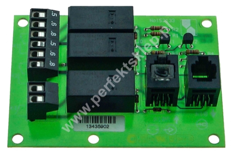
Connecting a voltmeter to the RJ11 connector confirmed my hypothesis. One 24 V pin to latch each relay and a common ground pin.
As you may know, the RPi won’t accept a 24 V current. Using an optocoupler can easily bring that down to something usable as an GPIO input, 3.3 V.
I found a board at 13th of the price of the official board with built in LED’s for more convenient debugging.
Marantec 220 Comfort XB10 RJ11 pinout:
- Brown - GND when door is closed
- Green - GND when door is open
- Blue - GND when motor light is on
- Black - 24 V
- Yellow - Short with pin 6
- Red - Short with pin 5
Exposing the motor to HomeKit
Being able to read the door position directly from the motor was the hard part. Next step was to control the motor. This was done using a relay module connected to a GPIO output on the RPi.
Now when I can both determine the door position and control the motor from the RPi, it’s time to expose this interface to HomeKit using homebridge.
Unfortunately, I didn’t get around to finish this project before started to refurbish our garage.